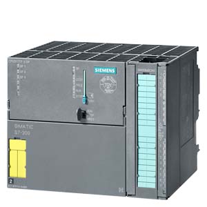
6ES7317-6TF14-0AB0 CPU317TF-2 DP, 1,5 MB

Product Code: 6ES7317-6TF14-0AB0

Availability: In Stock

Price: $100,000,000,000.00
Artikelnummer 6ES7317-6TF14-0AB0
SIMATIC S7-300, CPU 317TF-2 DP, CENTRAL PROCESSING UNIT FOR PLC AND TECHNOLOGY AND SAFETY, 1,5 MBYTE WORKING MEMORY, 1. INTERFACE MPI/DP 12MBIT/S 2. INTERFACE DP(DRIVE), INTEGRATED I/O FOR TECHNOLOGY FRONT CONNECTOR (1 X 40PIN) AND MICRO MEMORY CARD MIN. 8MB NECESSARY
Product type designation
General information
Hardware product version 01
Firmware version CPU: V2.7, integrated technology: V4.1.5
Engineering with
● Programming package STEP7 V 5.4 SP5 or higher, S7-Technology V4.2 or higher, Distributed Safety V5.4 SP5 or higher, S7-F Configuration Pack V5.5 SP7 or higher
Supply voltage
24 V DC Yes
permissible range, lower limit (DC) 20.4 V
permissible range, upper limit (DC) 28.8 V
External protection for supply cables (recommendation) 2 A min.
Load voltage L+
● Rated value (DC) 24 V
● Reverse polarity protection Yes
Digital outputs
Load voltage L+
— Rated value (DC) 24 V; 2L+
— Reverse polarity protection No; 2L+
Input current
Current consumption (in no-load operation), typ. 250 mA
Inrush current, typ. 2.5 A
I²t 1 A²·s
Power losses
Power loss, typ. 6 W
Memory
Type of memory other
Work memory
● Integrated 1 536 kbyte
● expandable No
● Size of retentive memory for retentive data blocks 256 kbyte
Load memory
● pluggable (MMC) Yes
● pluggable (MMC), max. 8 Mbyte
● Data management on MMC (after last programming), min. 10 y
Backup
● present Yes; Guaranteed by MMC (maintenance-free)
● without battery Yes; Program and data
CPU processing times
for bit operations, typ. 0.05 µs
for bit operations, max. 0.05 µs
for word operations, typ. 0.2 µs
for fixed point arithmetic, typ. 0.2 µs
for floating point arithmetic, typ. 1 µs
CPU-blocks
Number of blocks (total) 2 048; (DBs, FCs, FBs); the maximum number of loadable blocks can be reduced by the MMC used.
DB
● Number, max. 2 047; Number band: 1 to 2047
● Size, max. 64 kbyte
FB
● Number, max. 2 048; Number range: 0 to 2047
● Size, max. 64 kbyte
FC
● Number, max. 2 048; Number range: 0 to 2047
● Size, max. 64 kbyte
OB
● Description see instruction list
● Size, max. 64 kbyte
● Number of free cycle OBs 1; OB 1
● Number of time alarm OBs 1; OB 10
● Number of delay alarm OBs 2; OB 20, 21
● Number of time interrupt OBs 4; OB 32, 33, 34, 35
● Number of process alarm OBs 1; OB 40
● Number of DPV1 alarm OBs 3; OB 55, 56, 57
● Number isochronous mode OBs 1; OB 61
● Number of technology synchronous alarm OBs 1; OB 65
● Number of startup OBs 1; OB 100
● Number of asynchronous error OBs 5; OB 80, 82, 85, 86, 87
● Number of synchronous error OBs 2; OB 121, 122
Nesting depth
● per priority class 16
● additional within an error OB 4
Counters, timers and their retentivity
S7 counter
● Number 512; Number range: 0 to 511
Retentivity
— can be set Yes
— preset 8 (from Z 0 to Z 7)
Counting range
— can be set Yes
— lower limit 0
— upper limit 999
IEC counter
● present Yes
● Type SFB
● Number Unlimited (limited only by RAM capacity)
S7 times
● Number 512; Number range: 0 to 511
of which retentive without battery
— can be set Yes
Retentivity
— can be set Yes
— preset No retentivity
Time range
— lower limit 10 ms
— upper limit 9 990 s
IEC timer
● present Yes
● Type SFB
● Number Unlimited (limited only by RAM capacity)
Data areas and their retentivity
retentive data area, total All DBs, max. 256 KB
Flag
● Number, max. 4 096 byte
● Retentivity available Yes; From MB 0 to MB 4095
● Retentivity preset MB 0 to MB 15
● Number of clock memories 8; 1 memory byte
Data blocks
● Number, max. 2 047; from DB 1 to DB 2047
● Size, max. 64 kbyte
● Retentivity adjustable Yes; via non-retain property on DB
● Retentivity preset Yes
Local data
● per priority class, max. 1 024 byte
Address area
I/O address area
● Inputs 8 192 byte
● Outputs 8 192 byte
of which, distributed
— Inputs 8 192 byte
— Outputs 8 192 byte
Process image
● Inputs, adjustable 2 048 byte
● Outputs, adjustable 2 048 byte
● Inputs, default 1 024 byte
● Outputs, default 1 024 byte
Default addresses of the integrated channels
— Digital inputs 66
— Digital outputs 66
Subprocess images
● Number of subprocess images, max. 1
Digital channels
● Inputs 65 536
● Outputs 65 536
● Inputs, of which central 512
● Outputs, of which central 512
Analog channels
● Inputs 4 096
● Outputs 4 096
● Inputs, of which central 64
● Outputs, of which central 64
Hardware configuration
Expansion devices, max. 0
Number of DP masters
● Integrated 2; 1 DP and 1 DP (drive)
● Via CP 2; for DP
Number of operable FMs and CPs (recommended)
● FM 8
● CP, point-to-point 8
● CP, LAN 8
Rack
● Racks, max. 1
● Modules per rack, max. 8
Time of day
Clock
● Hardware clock (real-time clock) Yes
● battery-backed and synchronizable Yes
● Deviation per day, max. 10 s
● Backup time 6 wk; At 40 °C ambient temperature
● Behavior of the clock following POWER-ON Clock continues running after POWER OFF
● Behavior of the clock following expiry of backup period Clock continues to run with the time at which the power failure occurred
Operating hours counter
● Number 4
● Number/Number range 0 to 3
● Range of values 0 to 2^31 hours (when using SFC 101)
● Granularity 1 hour
● retentive Yes; Must be restarted at each restart
Clock synchronization
● supported Yes
● to MPI, master Yes
● to MPI, slave Yes
● to DP, master Yes
● to DP, slave Yes; Only time-of-day slave
● in AS, master Yes
● in AS, slave Yes
Digital inputs
Number of digital inputs 4
● of which, inputs usable for technological functions 4
Input characteristic curve in accordance with IEC 61131, type 1 Yes
Number of simultaneously controllable inputs
horizontal installation
— up to 40 °C, max. 4
— up to 60 °C, max. 4
vertical installation
— up to 40 °C, max. 4
Input voltage
● Rated value (DC) 24 V
● for signal "0" -3 to +5V
● for signal "1" 15 to 30 V
Input current
● for signal "1", typ. 7 mA
Input delay (for rated value of input voltage)
for counter/technological functions
— at "0" to "1", max. 10 µs; Typical
— at "1" to "0", max. 10 µs; Typical
Cable length
● Cable length, shielded, max. 1 000 m
Digital outputs
Number of digital outputs 8
● of which high-speed outputs 8
Functions For technology functions, e.g. high-speed cam switch signals
short-circuit protection Yes
● Response threshold, typ. 1,0 A
Limitation of inductive shutdown voltage to 48 V
Controlling a digital input No
Switching capacity of the outputs
● Lamp load, max. 5 W
Load resistance range
● lower limit 48 Ω
● upper limit 4 kΩ
Output voltage
● for signal "0", max. 3 V; 2L+
● for signal "1", min. Rated voltage -2.5 V (2L+)
Output current
● for signal "1" rated value 0.5 A
● for signal "1" permissible range for 0 to 60 °C, min. 5 mA
● for signal "1" permissible range for 0 to 60 °C, max. 0.6 A
● for signal "0" residual current, max. 0.3 mA
Parallel switching of 2 outputs
● for increased power No
● for redundant control of a load No
Switching frequency
● with resistive load, max. 100 Hz
● with inductive load, max. 0.2 Hz; to IEC 947-5-1, DC-13
● on lamp load, max. 100 Hz
Aggregate current of outputs (per group)
horizontal installation
— up to 40 °C, max. 4 A
— up to 60 °C, max. 3 A
all other mounting positions
— up to 40 °C, max. 3 A
Cable length
● Cable length, shielded, max. 1 000 m
Analog inputs
Number of analog inputs 0
Analog outputs
Number of analog outputs 0
Encoder
Connectable encoders
● 2-wire sensor No
Interfaces
Number of USB interfaces 0
Number of parallel interfaces 0
Number of 20 mA interfaces (TTY) 0
Number of RS 232 interfaces 0
Number of RS 422 interfaces 0
Number of other interfaces 0
1st interface
Interface type Integrated RS 485 interface
Physics RS 485
Isolated Yes
Power supply to interface (15 to 30 V DC), max. 200 mA
Functionality
● MPI Yes
● DP master Yes
● DP slave Yes
● Point-to-point connection No
MPI
● Number of connections 32
● Transmission rate, max. 12 Mbit/s
Services
— PG/OP communication Yes
— Routing Yes
— Global data communication Yes
— S7 basic communication Yes
— S7 communication Yes
— S7 communication, as client No; but via CP and loadable FB
— S7 communication, as server Yes
DP master
● Transmission rate, max. 12 Mbit/s
● Number of DP slaves, max. 124
Services
— PG/OP communication Yes
— Routing Yes
— Global data communication No
— S7 basic communication Yes; I blocks only
— S7 communication Yes
— S7 communication, as client No; but via CP and loadable FB
— S7 communication, as server Yes
— Equidistance mode support Yes
— Isochronous mode Yes; OB 61
— SYNC/FREEZE Yes
— Activation/deactivation of DP slaves Yes
— Number of DP slaves that can be simultaneously activated/deactivated, max. 4
— DPV1 Yes
Address area
— Inputs, max. 8 192 byte
— Outputs, max. 8 192 byte
User data per DP slave
— Inputs, max. 244 byte
— Outputs, max. 244 byte
DP slave
● GSD file http://www.siemens.com/profibus-gsd
● Transmission rate, max. 12 Mbit/s
● Automatic baud rate search Yes; only with passive interface
● Address area, max. 32
● User data per address area, max. 32 byte
Services
— PG/OP communication Yes
— Routing Yes; Only with active interface
— Global data communication No
— S7 basic communication No
— S7 communication Yes; Only server, configured on one side
— S7 communication, as client Yes; but via CP and loadable FB
— S7 communication, as server Yes; Connection configured on one side only
— Direct data exchange (slave-to-slave communication) Yes
— DPV1 No
Transfer memory
— Inputs 244 byte
— Outputs 244 byte
2nd interface
Interface type Integrated RS 485 interface
Physics RS 485
Isolated Yes
Power supply to interface (15 to 30 V DC), max. 200 mA
Functionality
● MPI No
● DP master Yes; DP(DRIVE)-Master
● DP slave No
● Point-to-point connection No
DP master
● Transmission rate, max. 12 Mbit/s
● Number of DP slaves, max. 64
Services
— PG/OP communication No
— Routing Yes
— Global data communication No
— S7 basic communication No
— S7 communication No
— Equidistance mode support Yes
— Isochronous mode Yes
— SYNC/FREEZE No
— Activation/deactivation of DP slaves Yes
— DPV1 No
Address area
— Inputs, max. 1 024 byte
— Outputs, max. 1 024 byte
User data per DP slave
— Inputs, max. 244 byte
— Outputs, max. 244 byte
Communication functions
PG/OP communication Yes
Global data communication
● supported Yes
● Number of GD loops, max. 8
● Number of GD packets, max. 8
● Number of GD packets, transmitter, max. 8
● Number of GD packets, receiver, max. 8
● Size of GD packets, max. 22 byte
● Size of GD packet (of which consistent), max. 22 byte
S7 basic communication
● supported Yes
● User data per job, max. 76 byte
● User data per job (of which consistent), max. 76 byte; 76 bytes (with X_SEND or X_RCV), 76 bytes (with X_PUT or X_GET as server)
S7 communication
● supported Yes
● as server Yes
● As client Yes; Via CP and loadable FB
● User data per job, max. 180 byte; With PUT/GET
● User data per job (of which consistent), max. 160 byte
S5-compatible communication
● supported Yes; via CP and loadable FC
Number of connections
● overall 32
● usable for PG communication 31
— reserved for PG communication 1
— Adjustable for PG communication, min. 1
— Adjustable for PG communication, max. 31
● usable for OP communication 31
— reserved for OP communication 1
— adjustable for OP communication, min. 1
— adjustable for OP communication, max. 31
● usable for S7 basic communication 30
— Reserved for S7 basic communication 0
— adjustable for S7 basic communication, min. 0
— adjustable for S7 basic communication, max. 30
● usable for routing 8
S7 message functions
Number of login stations for message functions, max. 32; Depending on the configured connections for PG/OP and S7 basic communication
Process diagnostic messages Yes
simultaneously active Alarm-S blocks, max. 60
Test commissioning functions
Status block Yes; Up to 2 simultaneously
Single step Yes
Number of breakpoints 2; without continuation
Status/control
● Status/control variable Yes
● Variables Inputs, outputs, memory bits, DB, times, counters
● Number of variables, max. 30
● of which status variables, max. 30
● of which control variables, max. 14
Forcing
● Forcing Yes
● Force, variables Inputs, outputs
● Number of variables, max. 10
Diagnostic buffer
● present Yes
● Number of entries, max. 100
— can be set No
— Of which powerfail-proof 100
Interrupts/diagnostics/status information
Alarms
● Alarms No
Diagnostic messages
● Diagnostic functions No
Diagnostics indication LED
● Status indicator digital output (green) Yes
● Status indicator digital input (green) Yes
Galvanic isolation
Galvanic isolation digital inputs
● between the channels and the backplane bus Yes
Galvanic isolation digital outputs
● between the channels and the backplane bus Yes
Permissible potential difference
between different circuits 75 VDC / 60 VAC
Isolation
Isolation checked with 500 V DC
Ambient conditions
Operating temperature
● Min. 0 °C
● max. 60 °C
Configuration
Configuration software
● STEP 7 Yes
programming
● Command set see instruction list
● Nesting levels 8
● System functions (SFC) see instruction list
● System function blocks (SFB) see instruction list
Programming language
— LAD Yes
— FBD Yes
— STL Yes
— SCL Yes
— CFC Yes
— GRAPH Yes
— HiGraph® Yes
Know-how protection
● User program protection/password protection Yes
Cycle time monitoring
● lower limit 1 ms
● upper limit 6 000 ms
● can be set Yes
● preset 150 ms
Dimensions
Width 160 mm
Height 125 mm
Depth 130 mm
Weights
Weight, approx. 750 g
last modified: 14.10.2014

Write a review

Note: HTML is not translated!

Rating: Bad Good

Enter the code in the box below: