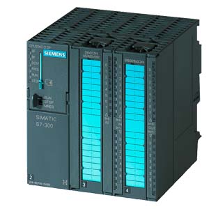
6ES7314-6CG03-0AB0 CPU314C-2DP, 24DI/16DO/4AI/2AO, 96 KB

Product Code: 6ES7314-6CG03-0AB0

Availability: In Stock

Price: $995.99
  
 
Artikelnummer 6ES7314-6CG03-0AB0
SIMATIC S7-300, CPU 314C-2DP COMPACT CPU WITH MPI, 24 DI/16 DO, 4AI, 2AO, 1 PT100, 4 FAST COUNTERS (60 KHZ), INTEGRATED DP INTERFACE, INTEGRATED 24V DC POWER SUPPLY, 96 KBYTE WORKING MEMORY, FRONT CONNECTOR (2 X 40PIN) AND MICRO MEMORY CARD REQUIRED
General information
Hardware product version 01
Firmware version V2.6
Engineering with
● Programming package STEP 7 V5.3 SP2 or higher with HW update
Supply voltage
24 V DC Yes
permissible range, lower limit (DC) 20.4 V
permissible range, upper limit (DC) 28.8 V
External protection for supply cables (recommendation) Miniature circuit breaker, type C; min. 2 A; miniature circuit breaker type B, min. 4 A
Load voltage L+
● Rated value (DC) 24 V
● permissible range, lower limit (DC) 20.4 V
● permissible range, upper limit (DC) 28.8 V
Digital inputs
Load voltage L+
— Rated value (DC) 24 V
— Reverse polarity protection Yes
Digital outputs
Load voltage L+
— Rated value (DC) 24 V
— Reverse polarity protection No
Analog outputs
Load voltage L+
— Rated value (DC) 24 V
— Reverse polarity protection Yes
Input current
Current consumption (rated value) 1 000 mA
Current consumption (in no-load operation), typ. 150 mA
Inrush current, typ. 11 A
I²t 0.7 A²·s
from supply voltage L+, max. 1 000 mA
Digital inputs
● from load voltage L+ (without load), max. 70 mA
Digital outputs
● from load voltage L+, max. 100 mA
Power losses
Power loss, typ. 14 W
Memory
Type of memory other
Work memory
● Integrated 96 kbyte
● expandable No
Load memory
● pluggable (MMC) Yes
● pluggable (MMC), max. 8 Mbyte
● Data management on MMC (after last programming), min. 10 y
Backup
● present Yes; Guaranteed by MMC (maintenance-free)
● without battery Yes; Program and data
CPU processing times
for bit operations, typ. 0.1 µs
for word operations, typ. 0.2 µs
for fixed point arithmetic, typ. 2 µs
for floating point arithmetic, typ. 3 µs
CPU-blocks
Number of blocks (total) 1 024; (DBs, FCs, FBs); the maximum number of loadable blocks can be reduced by the MMC used.
DB
● Number, max. 511; Number range: 1 to 511
● Size, max. 16 kbyte
FB
● Number, max. 1 024; Number range: 0 to 2047
● Size, max. 16 kbyte
FC
● Number, max. 1 024; Number range: 0 to 2047
● Size, max. 16 kbyte
OB
● Size, max. 16 kbyte
● Number of free cycle OBs 1; OB 1
● Number of time alarm OBs 1; OB 10
● Number of delay alarm OBs 1; OB 20
● Number of time interrupt OBs 1; OB 35
● Number of process alarm OBs 1; OB 40
● Number of DPV1 alarm OBs 3; OB 55, 56, 57
● Number of startup OBs 1; OB 100
● Number of asynchronous error OBs 5; OB 80, 82, 85, 86, 87
● Number of synchronous error OBs 2; OB 121, 122
Nesting depth
● per priority class 8
● additional within an error OB 4
Counters, timers and their retentivity
S7 counter
● Number 256
of which retentive without battery
— can be set Yes
— lower limit 0
— upper limit 255
— preset 8
Retentivity
— can be set Yes
— lower limit 0
— upper limit 255
— preset 8
Counting range
— lower limit 0
— upper limit 999
IEC counter
● present Yes
● Type SFB
● Number Unlimited (limited only by RAM capacity)
S7 times
● Number 256
of which retentive without battery
— can be set Yes
— lower limit 0
— upper limit 255
Retentivity
— can be set Yes
— lower limit 0
— upper limit 255
— preset No retentivity
Time range
— lower limit 10 ms
— upper limit 9 990 s
IEC timer
● present Yes
● Type SFB
● Number Unlimited (limited only by RAM capacity)
Data areas and their retentivity
retentive data area, total All, max. 64 KB
Flag
● Number, max. 256 byte
● Retentivity available Yes; MB 0 to MB 255
● Retentivity preset MB 0 to MB 15
● Number of clock memories 8; 1 memory byte
Data blocks
● Number, max. 511; Number range: 1 to 511
● Size, max. 16 kbyte
● Retentivity adjustable Yes; via non-retain property on DB
● Retentivity preset Yes
Local data
● per priority class, max. 510 byte
Address area
I/O address area
● Inputs 1 kbyte
● Outputs 1 kbyte
of which, distributed
— Inputs 979 byte
— Outputs 986 byte
Process image
● Inputs 128 byte
● Outputs 128 byte
Default addresses of the integrated channels
— Digital inputs 124.0 to 126.7
— Digital outputs 124.0 to 125.7
— Analog inputs 752 to 761
— Analog outputs 752 to 755
Digital channels
● Inputs 7 856
● Outputs 7 904
● Inputs, of which central 1 016
● Outputs, of which central 1 008
Analog channels
● Inputs 494
● Outputs 495
● Inputs, of which central 253
● Outputs, of which central 250
Hardware configuration
Expansion devices, max. 3
Number of DP masters
● Integrated 1
● Via CP 4
Number of operable FMs and CPs (recommended)
● FM 8
● CP, point-to-point 8
● CP, LAN 10
Rack
● Racks, max. 4
● Modules per rack, max. 8; In rack 3 max. 7
Time of day
Clock
● Hardware clock (real-time clock) Yes
● battery-backed and synchronizable Yes
● Deviation per day, max. 10 s
● Backup time 6 wk; At 40 °C ambient temperature
Operating hours counter
● Number 1
● Number/Number range 0
● Range of values 0 to 2^31 hours (when using SFC 101)
● Granularity 1 hour
● retentive Yes; Must be restarted at each restart
Clock synchronization
● supported Yes
● to MPI, master Yes
● to MPI, slave Yes
● to DP, master Yes; With DP slave only slave clock
● to DP, slave Yes
● in AS, master Yes
Digital inputs
Number of digital inputs 24
● of which, inputs usable for technological functions 16
integrated channels (DI) 24
Input characteristic curve in accordance with IEC 61131, type 1 Yes
Number of simultaneously controllable inputs
horizontal installation
— up to 40 °C, max. 24
— up to 60 °C, max. 12
vertical installation
— up to 40 °C, max. 12
Input voltage
● Rated value, DC 24 V
● for signal "0" -3 to +5V
● for signal "1" 15 to 30 V
Input current
● for signal "1", typ. 9 mA
Input delay (for rated value of input voltage)
for standard inputs
— Parameterizable Yes; 0.1 / 0.3 / 3 / 15 ms
— Rated value 3 ms
for counter/technological functions
— at "0" to "1", max. 8 µs
Cable length
● Cable length, shielded, max. 1 000 m; 50 m for technological functions
● Cable length unshielded, max. 600 m; For technological functions: No
Technological functions
— shielded, max. 50 m
— Unshielded, max. not allowed
Standard DI
— shielded, max. 1 000 m
— Unshielded, max. 600 m
Digital outputs
Number of digital outputs 16
● of which high-speed outputs 4
integrated channels (DO) 16
short-circuit protection Yes; Clocked electronically
● Response threshold, typ. 1 A
Limitation of inductive shutdown voltage to L+ (-48 V)
Controlling a digital input Yes
Switching capacity of the outputs
● Lamp load, max. 5 W
Load resistance range
● lower limit 48 Ω
● upper limit 4 kΩ
Output voltage
● for signal "1", min. L+ (-0.8 V)
Output current
● for signal "1" rated value 500 mA
● for signal "1" permissible range, min. 5 mA
● for signal "1" permissible range, max. 0.6 A
● for signal "1" minimum load current 5 mA
● for signal "0" residual current, max. 0.5 mA
Parallel switching of 2 outputs
● for increased power No
● for redundant control of a load Yes
Switching frequency
● with resistive load, max. 100 Hz
● with inductive load, max. 0.5 Hz
● on lamp load, max. 100 Hz
● of the pulse outputs, with resistive load, max. 2.5 kHz
Aggregate current of outputs (per group)
horizontal installation
— up to 40 °C, max. 3 A
— up to 60 °C, max. 2 A
vertical installation
— up to 40 °C, max. 2 A
Cable length
● Cable length, shielded, max. 1 000 m
● Cable length unshielded, max. 600 m
Analog inputs
Integrated channels (AI) 4+1
Number of analog inputs for voltage/current measurement 4
Number of analog inputs for resistance/resistance thermometer measurement 1
permissible input frequency for current input (destruction limit), max. 5 V; Permanent
permissible input voltage for voltage input (destruction limit), max. 30 V; Permanent
permissible input current for voltage input (destruction limit), max. 0.5 mA; Permanent
permissible input current for current input (destruction limit), max. 50 mA; Permanent
Technical unit for temperature measurement adjustable Yes; Degrees Celsius / degrees Fahrenheit / Kelvin
Input ranges
● Current Yes
● Resistance thermometer Yes; Pt 100 / 10 MΩ
● Resistance Yes
Input ranges (rated values), voltages
● 0 to +10 V Yes
● Input resistance (0 to 10 V) 100 kΩ
Input ranges (rated values), currents
● 0 to 20 mA Yes
● Input resistance (0 to 20 mA) 100 Ω
● -20 to +20 mA Yes
● Input resistance (-20 to +20 mA) 100 Ω
● 4 to 20 mA Yes
● Input resistance (4 to 20 mA) 100 Ω
Input ranges (rated values), resistance thermometer
● Pt 100 Yes
● Input resistance (Pt 100) 10 MΩ
Input ranges (rated values), resistors
● No-Load voltage, typ. 2.5 V
● Measured current, typ. 1.8 to 3.3 mA
● 0 to 600 ohms Yes
● Input resistance (0 to 600 ohms) 10 MΩ
Thermocouple (TC)
Temperature compensation
— Parameterizable No
Characteristic linearization
● Parameterizable Yes; by software
— for resistance thermometer Pt 100
Cable length
● Cable length, shielded, max. 100 m
Analog outputs
Number of analog outputs 2
Integrated channels (AO) 2
Voltage output, short-circuit protection Yes
Voltage output, short-circuit current, max. 55 mA
Current output, no-load voltage, max. 17 V
Output ranges, voltage
● 0 to 10 V Yes
● -10 to +10 V Yes
Output ranges, current
● 0 to 20 mA Yes
● -20 to +20 mA Yes
● 4 to 20 mA Yes
Connection of actuators
● for voltage output two-wire connection Yes; Without compensation of the line resistances
● for voltage output four-wire connection No
● for current output two-wire connection Yes
Load impedance (in rated range of output)
● with voltage outputs, min. 1 kΩ
● with voltage outputs, capacitive load, max. 0.1 µF
● with current outputs, max. 300 Ω
● with current outputs, inductive load, max. 0.1 mH
Destruction limits against externally applied voltages and currents
● Voltages at the outputs towards MANA 16 V; Permanent
● Current, max. 50 mA; Permanent
Cable length
● Cable length, shielded, max. 200 m
Analog value creation
Measurement principle Actual value encryption (successive approximation)
Integration and conversion time/resolution per channel
● Resolution with overrange (bit including sign), max. 12 bit
● Integration time, parameterizable Yes; 2,5 / 16,6 / 20 ms
● permissible input frequency, max. 400 Hz
● Interference voltage suppression for interference frequency f1 in Hz 400 / 60 / 50 Hz
● Conversion time (per channel) 1 ms
● Time constant of the input filter 0.38 ms
● Basic execution time of the module (all channels released) 1 ms
Settling time
● for resistive load 0.6 ms
● for capacitive load 1 ms
● for inductive load 0.5 ms
Encoder
Connection of signal encoders
● for voltage measurement Yes
● for current measurement as 2-wire transducer Yes; with external supply
● for current measurement as 4-wire transducer Yes
● for resistance measurement with two-wire connection Yes; Without compensation of the line resistances
● for resistance measurement with three-wire connection No
● for resistance measurement with four-wire connection No
Connectable encoders
● 2-wire sensor Yes
— Permissible quiescent current (2-wire sensor), max. 1.5 mA
Errors/accuracies
Temperature error (relative to input range), (+/-) 0.006 %/K
Crosstalk between the inputs, min. 60 dB
Repeat accuracy in steady state at 25 °C (relative to input area), (+/-) 0.06 %
Output ripple (based on output area, bandwidth 0 to 50 kHz), (+/-) 0.1 %
Linearity error (relative to output range), (+/-) 0.15 %
Temperature error (relative to output range), (+/-) 0.01 %/K
Crosstalk between the outputs, min. 60 dB
Repeat accuracy in steady state at 25 °C (relative to output area), (+/-) 0.06 %
Operational limit in overall temperature range
● Voltage, relative to input area, (+/-) 1 %
● Current, relative to input area, (+/-) 1 %
● Resistance, relative to input area, (+/-) 5 %
● Voltage, relative to output area, (+/-) 1 %
● Current, relative to output area, (+/-) 1 %
Basic error limit (operational limit at 25 °C)
● Voltage, relative to input area, (+/-) 0.7 %; Linearity error +/- 0.06 %
● Current, relative to input area, (+/-) 0.7 %; Linearity error +/- 0.06 %
● Resistance, relative to input area, (+/-) 3 %; Linearity error +/- 0.2%
● Resistance thermometer, relative to input area, (+/-) 3 %
● Voltage, relative to output area, (+/-) 0.7 %
● Current, relative to output area, (+/-) 0.7 %
Interference voltage suppression for f = n x (f1 +/- 1 %), f1 = interference frequency
● Series mode interference (peak value of interference < rated value of input range), min. 30 dB
● Common mode interference, min. 40 dB
Interfaces
Number of USB interfaces 0
Number of parallel interfaces 0
Number of 20 mA interfaces (TTY) 0
Number of RS 232 interfaces 0
Number of RS 422 interfaces 0
Number of other interfaces 0
MPI
● Cable length, max. 50 m; without repeater
1st interface
Interface type Integrated RS 485 interface
Physics RS 485
Isolated No
Power supply to interface (15 to 30 V DC), max. 200 mA
Functionality
● MPI Yes
● DP master No
● DP slave No
● Point-to-point connection No
MPI
● Number of connections 12
● Transmission rate, max. 187.5 kbit/s
Services
— PG/OP communication Yes
— Routing Yes
— Global data communication Yes
— S7 basic communication Yes
— S7 communication Yes
— S7 communication, as client No
— S7 communication, as server Yes
2nd interface
Interface type Integrated RS 485 interface
Physics RS 485
Isolated Yes
Power supply to interface (15 to 30 V DC), max. 200 mA
Number of connection resources 12
Functionality
● MPI No
● DP master Yes
● DP slave Yes
● PROFINET IO Controller No
● PROFINET CBA No
● Point-to-point connection No
DP master
● Number of connections, max. 12; For PG/OP communication
● Transmission rate, max. 12 Mbit/s
● Number of DP slaves, max. 32
Services
— PG/OP communication Yes
— Routing Yes
— Global data communication No
— S7 basic communication Yes; I blocks only
— S7 communication Yes
— S7 communication, as client No
— S7 communication, as server Yes
— Equidistance mode support Yes
— Isochronous mode No
— SYNC/FREEZE Yes
— Activation/deactivation of DP slaves Yes
— Direct data exchange (slave-to-slave communication) Yes
— DPV1 Yes
Address area
— Inputs, max. 1 kbyte
— Outputs, max. 1 kbyte
User data per DP slave
— Inputs, max. 244 byte
— Outputs, max. 244 byte
DP slave
● Number of connections 12
● GSD file The latest GSD file is available at: http://www.siemens.com/profibus-gsd
● Transmission rate, max. 12 Mbit/s
● Automatic baud rate search Yes; only with passive interface
● Address area, max. 32
● User data per address area, max. 32 byte
Services
— PG/OP communication Yes
— Routing Yes; Only with active interface
— Global data communication No
— S7 basic communication No
— S7 communication Yes
— S7 communication, as client No
— S7 communication, as server Yes
— Direct data exchange (slave-to-slave communication) Yes
— DPV1 No
Transfer memory
— Inputs 244 byte
— Outputs 244 byte
Communication functions
PG/OP communication Yes
Global data communication
● supported Yes
● Number of GD loops, max. 4
● Number of GD packets, max. 4
● Number of GD packets, transmitter, max. 4
● Number of GD packets, receiver, max. 4
● Size of GD packets, max. 22 byte
● Size of GD packet (of which consistent), max. 22 byte
S7 basic communication
● supported Yes
● User data per job, max. 76 byte
● User data per job (of which consistent), max. 76 byte; 76 bytes (with X_SEND or X_RCV); 64 bytes (with X_PUT or X_GET as server)
S7 communication
● supported Yes
● as server Yes
● As client Yes; Via CP and loadable FB
● User data per job, max. 180 kbyte; With PUT/GET
● User data per job (of which consistent), max. 64 byte
S5-compatible communication
● supported Yes; via CP and loadable FC
Number of connections
● overall 12
● usable for PG communication 11
— reserved for PG communication 1
— Adjustable for PG communication, min. 1
— Adjustable for PG communication, max. 11
● usable for OP communication 11
— reserved for OP communication 1
— adjustable for OP communication, min. 1
— adjustable for OP communication, max. 11
● usable for S7 basic communication 8
— Reserved for S7 basic communication 0
— adjustable for S7 basic communication, min. 0
— adjustable for S7 basic communication, max. 8
● usable for routing 4; max.
S7 message functions
Number of login stations for message functions, max. 12; Depending on the configured connections for PG/OP and S7 basic communication
Process diagnostic messages Yes
simultaneously active Alarm-S blocks, max. 40
Test commissioning functions
Status block Yes
Single step Yes
Number of breakpoints 2
Status/control
● Status/control variable Yes
● Variables Inputs, outputs, memory bits, DB, times, counters
● Number of variables, max. 30
● of which status variables, max. 30
● of which control variables, max. 14
Forcing
● Forcing Yes
● Force, variables Inputs, outputs
● Number of variables, max. 10
Diagnostic buffer
● present Yes
● Number of entries, max. 100
Interrupts/diagnostics/status information
Diagnostics indication LED
● Status indicator digital output (green) Yes
● Status indicator digital input (green) Yes
Integrated Functions
Number of counters 4; See "Technological Functions" manual
Counter frequency (counter) max. 60 kHz
Frequency measurement Yes
Number of frequency meters 4; up to 60 kHz (see "Technological Functions" manual)
controlled positioning Yes
Integrated function blocks (closed-loop control) PID controller (see "Technological Functions" manual)
PID controller Yes
Number of pulse outputs 4; Pulse width modulation up to 2.5 kHz (see "Technological Functions" Manual)
Limit frequency (pulse) 2.5 kHz
Galvanic isolation
Galvanic isolation digital inputs
● Galvanic isolation digital inputs Yes
● between the channels No
● between the channels and the backplane bus Yes
Galvanic isolation digital outputs
● Galvanic isolation digital outputs Yes
● between the channels Yes
● between the channels, in groups of 8
● between the channels and the backplane bus Yes
Galvanic isolation analog inputs
● Galvanic isolation analog inputs Yes; common for analog I/O
● between the channels No
● between the channels and the backplane bus Yes
Galvanic isolation analog outputs
● Galvanic isolation analog outputs Yes; common for analog I/O
● between the channels No
● between the channels and the backplane bus Yes
Permissible potential difference
between different circuits 75 VDC / 60 VAC
between inputs and MANA (UCM) 8 V DC
between MANA and M internally (UISO) 75 VDC / 60 VAC
Isolation
Isolation checked with 600 V DC
Configuration
Configuration software
● STEP 7 Yes; V5.3 SP2 with HW update
programming
● Command set see instruction list
● Nesting levels 8
● System functions (SFC) see instruction list
● System function blocks (SFB) see instruction list
Programming language
— LAD Yes
— FBD Yes
— STL Yes
— SCL Yes
— CFC Yes
— GRAPH Yes
— HiGraph® Yes
Know-how protection
● User program protection/password protection Yes
Dimensions
Width 120 mm
Height 125 mm
Depth 130 mm
Weights
Weight, approx. 676 g
last modified: 25.09.2014

Write a review

Note: HTML is not translated!

Rating: Bad Good

Enter the code in the box below: